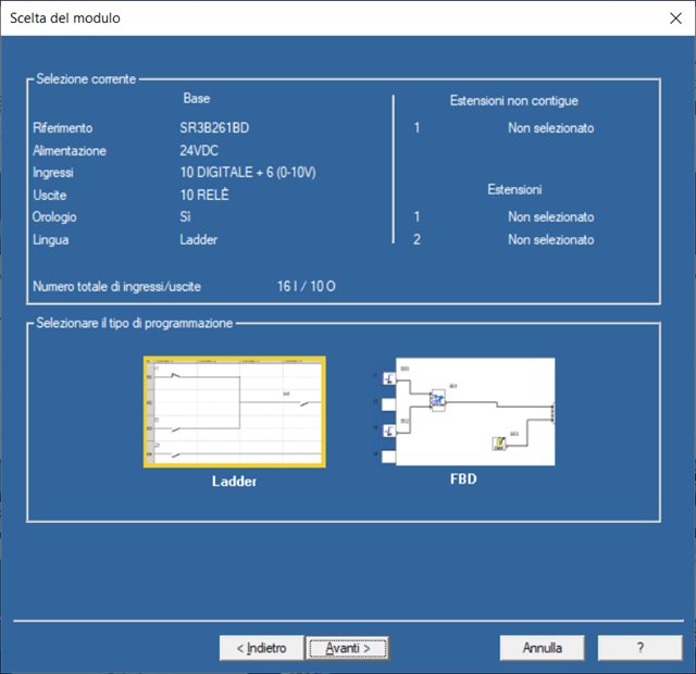
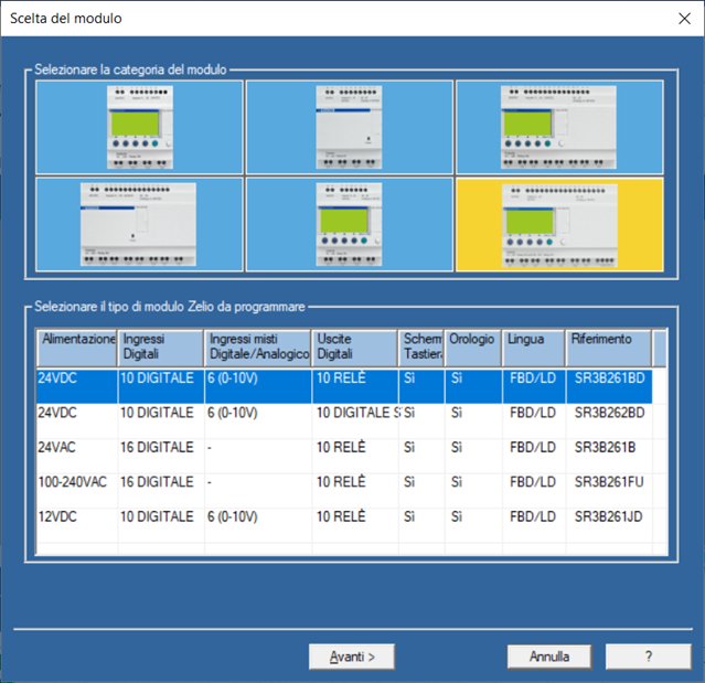
Some years ago, my colleague Edoardo and me decided to teach electronic students too, in addition to programming microcontrollers like Arduino or Microchip PIC, LabVIEW and Xilinx FPGAs, even PLC programming. So we bought PLCs Schneider Electric, small and versatile. My colleague is retired this year and it's up to me to prepare some lessons for the students. The PLC we use is the model SR3B261BD and the programming software is ZelioSoft2. Some features of the PLC SR3B261BD:
-
Nominal supply voltage 24VDC.
-
Number of digital inputs 16 digital resistive type; digital input voltage 24VDC, digital input current 4mA.
-
Analog input resolution 8 bit; LSB value 39 mV for analog input circuit; analog input range 0 ... 10V and 0 ... 24V.
-
Number of outputs 10 relays; output voltage limits 24 ... 250VAC (relay output), 5 ... 30VDC (relay output); composition and type of contacts: NO for relay output; thermal current output: 5A for 2 outputs for relay output, 8A for 8 outputs for relay output.
 |
 |
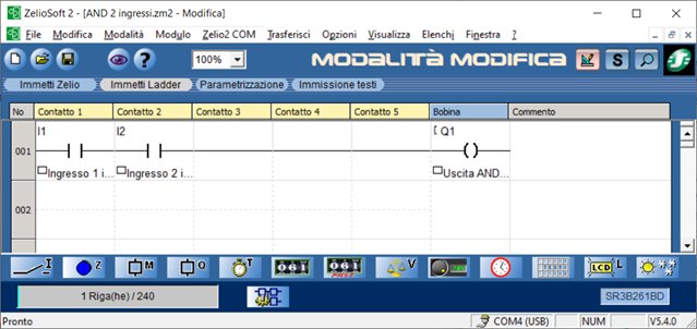
In PLC programming, each solution is entrusted to the experience and inventiveness of the programmer. However, it is possible to isolate some basic recurring configurations.
The first is AND combination: it is equivalent to the series of two contacts. The figure shows the relative ladder diagram:
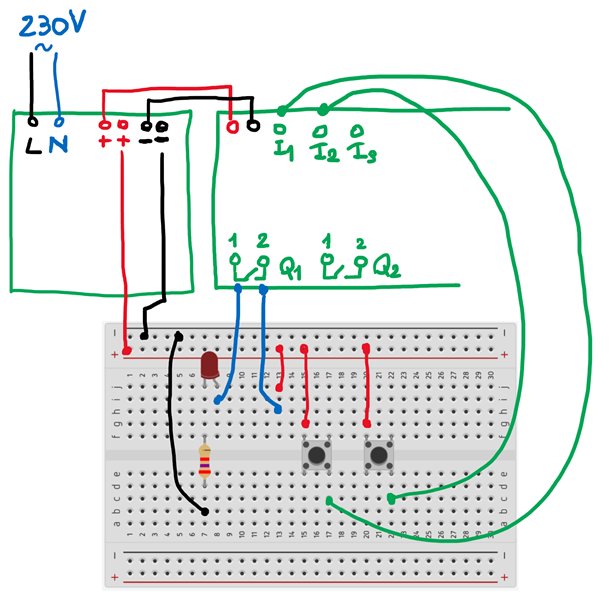
In the laboratory we generally use 24V lamps for the output and pushbuttons for electrical applications for the input, but it is also possible to use electronic devices mounted on breadboard, such as colored LEDs (e.g. red LED with 1.2V threshold voltage and current recommended 10mA protected with 2.7kOhm E12 1/4W resistor) and pushbuttons. The figure shows the circuit assembly diagram:
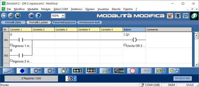
The second is OR combination: it is equivalent to the parallel of two contacts. The figure shows the relative ladder diagram:
The circuit assembly diagram is the same as that relating to the AND combination (see previous figure).