When I was a child, in 1980, I spent some time playing a fun game that asked me to watch, remember and repeat a random sequence proposed from time to time by the microcontroller in a challenge that was inexorably won by the machine! The game was invented in 1978 and was called Simon; today I read his story on Wikipedia: https://en.wikipedia.org/wiki/Simon_(game).The device creates a series of tones and lights and requires a user to repeat the sequence. If the user succeeds, the series becomes progressively longer and more complex. Once the user fails or the time limit runs out, the game is over. Here I propose a simple realization with Arduino uno that you can simulate in https://www.tinkercad.com/things/jKi6DJadMBu or realize in practice with four LEDs and four buttons, plus one for the reset of the game.

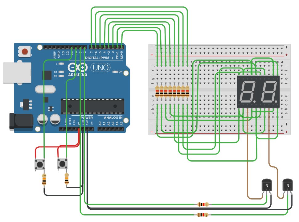
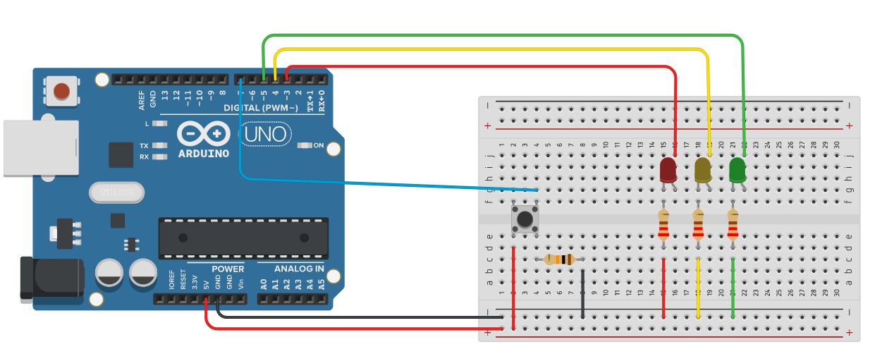
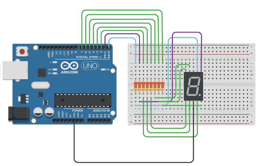
Below is the circuit and the sketch made with the students of 3AO Electronics of the school year 2020/21 at IIS Maxwell, Milan.

Image2 2


/*   
  V1.0 - Spadaro Filippo 28 may 2021
  
  btnNONE: nessun pulsante premuto  
  btnGREEN: stampa btnGREEN  
  btnYELLOW: stampa btnYELLOW
  btnRED:   btnRED   
  btnBLUE: btnBLUE   
  btnSELECT: stampa SELECT
*/ 

#define btnGREEN    2
#define btnYELLOW 3
#define btnRED    4
#define btnBLUE     5
#define btnSELECT   1
#define btnNONE     0

#define pinLEDGREEN   2
#define pinLEDYELLOW  3
#define pinLEDRED     4
#define pinLEDBLUE    5

// define the button debounce
int lcd_key = btnNONE; 
int lcd_key_precedente = btnNONE;
int adc_key_in  = 0;

// game variables
int sequenza[20];
int fineSequenza = 0, i, pulsantePremuto, contaPulsante;
bool indovinaSequenza = false;

// random sequence 
void generaSequenza(int inizio, int fine) {
  for (i=0; i<20; i++)
  {
    sequenza[i]=random(inizio,fine+1);
    Serial.print(sequenza[i]);
    Serial.print(" ");    
  }
  Serial.println();
}

// print sequence 
void stampaSequenza(int inizio, int fine) {
  for (i=inizio; i<fine; i++) {
      digitalWrite(sequenza[i],HIGH);
        delay(500);
        digitalWrite(sequenza[i],LOW);
        delay(500);
     }
}

// light only one LED
void illuminaUnLed(int LED1Illuminato, int LED2Spento, int LED3Spento, int LED4Spento) 
     {
     digitalWrite(LED1Illuminato,HIGH);
         digitalWrite(LED2Spento,LOW);
         digitalWrite(LED3Spento,LOW);
         digitalWrite(LED4Spento,LOW);
         delay(300);
         digitalWrite(LED1Illuminato,LOW);
         digitalWrite(LED2Spento,LOW);
         digitalWrite(LED3Spento,LOW);
         digitalWrite(LED4Spento,LOW);
       delay(300);
}

// light all LED
void illuminaTuttiLed(int LED1Illuminato, int LED2Illuminato, int LED3Illuminato, int LED4Illuminato) 
     {
     digitalWrite(LED1Illuminato,HIGH);
         digitalWrite(LED2Illuminato,HIGH);
         digitalWrite(LED3Illuminato,HIGH);
         digitalWrite(LED4Illuminato,HIGH);
         delay(300);
         digitalWrite(LED1Illuminato,LOW);
         digitalWrite(LED2Illuminato,LOW);
         digitalWrite(LED3Illuminato,LOW);
         digitalWrite(LED4Illuminato,LOW);
       delay(300);
}

void giocoDiLuciAccensione(int LED1, int LED2, int LED3, int LED4) 
  {
    digitalWrite(LED1,HIGH);
    delay(200);
    digitalWrite(LED1,LOW);
    digitalWrite(LED2,HIGH);
    delay(200);
    digitalWrite(LED2,LOW);
    digitalWrite(LED3,HIGH);
    delay(200);
    digitalWrite(LED3,LOW);
    digitalWrite(LED4,HIGH);
    delay(200);
    digitalWrite(LED4,LOW);
    delay(200);
    digitalWrite(LED1,HIGH);
    digitalWrite(LED2,HIGH);
    digitalWrite(LED3,HIGH);
    digitalWrite(LED4,HIGH);
    delay(200);
    digitalWrite(LED1,LOW);
    digitalWrite(LED2,LOW);
    digitalWrite(LED3,LOW);
    digitalWrite(LED4,LOW);
    delay(200);
    digitalWrite(LED1,HIGH);
    digitalWrite(LED2,HIGH);
    digitalWrite(LED3,HIGH);
    digitalWrite(LED4,HIGH);
    delay(200);
    digitalWrite(LED1,LOW);
    digitalWrite(LED2,LOW);
    digitalWrite(LED3,LOW);
    digitalWrite(LED4,LOW);
    delay(2000);
}   
  
// read the button value
int read_LCD_buttons()
{
 adc_key_in = analogRead(0);          // read analog A0 value
 // Serial.println(adc_key_in);     // per il debug
 /* Resistori tra 5V e 0V: 2.2k - 1k - 1k - 1k - 2.2k */
 if (adc_key_in > 1000) return btnNONE; // 1023
if (adc_key_in < 50) return btnGREEN; // 0
if (adc_key_in < 350) return btnYELLOW; // 320
if (adc_key_in < 500) return btnRED; // 487
if (adc_key_in < 650) return btnBLUE; // 590
if (adc_key_in < 800) return btnSELECT; // 719 return btnNONE; } void setup() { Serial.begin(9600); Serial.println("Push start button");   // display "Push the buttons" pinMode(pinLEDGREEN,OUTPUT); pinMode(pinLEDYELLOW,OUTPUT); pinMode(pinLEDRED,OUTPUT); pinMode(pinLEDBLUE,OUTPUT); randomSeed(analogRead(1)); } void loop() { lcd_key = read_LCD_buttons();    // lettura pulsanti // Serial.println(lcd_key);      // per il debug  if ((lcd_key != btnNONE) && (lcd_key_precedente == btnNONE))    // Anti-rimbalzo  {   // A seconda del pulsante premuto, esegue un'azione   switch (lcd_key)                  {     case btnGREEN:       {        illuminaUnLed(pinLEDGREEN, pinLEDYELLOW, pinLEDRED, pinLEDBLUE);    pulsantePremuto= btnGREEN;        delay(200);                  if (sequenza[contaPulsante]==pulsantePremuto) {            if (indovinaSequenza==true) {              if (contaPulsante<fineSequenza-1) {                  contaPulsante++;               }                 else {                      fineSequenza++;                      stampaSequenza(0, fineSequenza);                      contaPulsante = 0;                   }               }             else {                illuminaTuttiLed(pinLEDBLUE, pinLEDRED, pinLEDYELLOW, pinLEDGREEN);             }                    }         else {               indovinaSequenza = false;                illuminaTuttiLed(pinLEDBLUE, pinLEDRED, pinLEDYELLOW, pinLEDGREEN);         }                  break;       }     case btnYELLOW:       {    illuminaUnLed(pinLEDYELLOW, pinLEDGREEN, pinLEDRED, pinLEDBLUE);    pulsantePremuto= btnYELLOW;         delay(200);                           if (sequenza[contaPulsante]==pulsantePremuto) {            if (indovinaSequenza==true) {              if (contaPulsante<fineSequenza-1) {                  contaPulsante++;               }                 else {                      fineSequenza++;                      stampaSequenza(0, fineSequenza);                      contaPulsante = 0;                   }               }             else {                illuminaTuttiLed(pinLEDBLUE, pinLEDRED, pinLEDYELLOW, pinLEDGREEN);             }         }         else {               indovinaSequenza = false;                illuminaTuttiLed(pinLEDBLUE, pinLEDRED, pinLEDYELLOW, pinLEDGREEN);         }                 break;       }     case btnRED:       {      illuminaUnLed(pinLEDRED, pinLEDYELLOW, pinLEDGREEN, pinLEDBLUE);    pulsantePremuto= btnRED;    delay(200);                  if (sequenza[contaPulsante]==pulsantePremuto) {            if (indovinaSequenza==true) {              if (contaPulsante<fineSequenza-1) {                  contaPulsante++;               }                 else {                      fineSequenza++;                      stampaSequenza(0, fineSequenza);                      contaPulsante = 0;                   }               }             else {                illuminaTuttiLed(pinLEDBLUE, pinLEDRED, pinLEDYELLOW, pinLEDGREEN);             }         }         else {               indovinaSequenza = false;                illuminaTuttiLed(pinLEDBLUE, pinLEDRED, pinLEDYELLOW, pinLEDGREEN);         }                 break;       }     case btnBLUE:       {    illuminaUnLed(pinLEDBLUE, pinLEDYELLOW, pinLEDGREEN, pinLEDRED);    pulsantePremuto= btnBLUE;         delay(200);                 if (sequenza[contaPulsante]==pulsantePremuto) {            if (indovinaSequenza==true) {              if (contaPulsante<fineSequenza-1) {                  contaPulsante++;               }                 else {                      fineSequenza++;                      stampaSequenza(0, fineSequenza);                      contaPulsante = 0;                   }               }             else {                illuminaTuttiLed(pinLEDBLUE, pinLEDRED, pinLEDYELLOW, pinLEDGREEN);             }         }         else {               indovinaSequenza = false;                illuminaTuttiLed(pinLEDBLUE, pinLEDRED, pinLEDYELLOW, pinLEDGREEN);         }                 break;       }     case btnSELECT:       {       giocoDiLuciAccensione(pinLEDBLUE, pinLEDRED, pinLEDYELLOW, pinLEDGREEN);                generaSequenza(pinLEDGREEN, pinLEDBLUE);        indovinaSequenza = true;      fineSequenza = 1;        stampaSequenza(0, fineSequenza);      contaPulsante = 0;                  break;       }            case btnNONE:       {       // nulla da eseguire       break;       }   }  } lcd_key_precedente = lcd_key; delay(50); }

20211030 161240

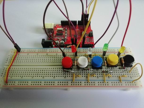
In the realization of the game input, I propose to acquire the signal of the chosen button by using a single analog pin instead of using 5 digital pins, one for each button. In this way I save 5 Arduino digital pins against an alalogic one. The LEDs, on the other hand, are connected to the digital pins. To read the buttons I create a pull-up voltage divider with 5 resistors placed between 5V and 0: 2.2kOhm - 1kOhm - 1kOhm - 1kOhm - 2.2kOhm and acquire the voltage levels with analogRead() which change according to the button that is held down. The function that takes care of this is read_LCD_buttons() which returns the value of the pressed button, and the game is then handled by a switch-case.
A debounce algorithm (managed with the use of the two variables lcd_key and lcd_key_precedente) allows the correct reception of the button chosen by the player: you can see it at the beginning and at the end of the loop().

We program an Arduino sketch that creates an up/down counter from 0 to 99 managed by 2 buttons, one for increasing and the other for decreasing, and the system prints the status of the count on 2 seven-segment displays. The circuit is shown in the figure and can also be implemented in practice.
The two buttons are mounted in pull-down with 10kOhm resistors. Arduino accepts a voltage of 5V for the high level and 0V for the low level on the digital pins. The display LEDs are protected with 220Ohm resistors. Arduino generates a voltage of 5V on the digital pins for the high level and supplies a current of about 40mA.

2 display 7 segmenti up'n down.jpg

Here is the link for the simulation with Tinkercad: https://www.tinkercad.com/things/i5TAs15Ckri

In the sketch below I found a software solution to button bouncing. For information on how to program the debounce of a button you can see my article: https://www.filipposfactory.com/index.php/8-arduino/37-switch-debouncing

Also for information on how to use the Arduino Uno port registers see this article of mine: https://www.filipposfactory.com/index.php/8-arduino/35-counter-0-9-with-7-segments-display-and-arduino-uno or you go to Arduino site: https://www.arduino.cc/en/Reference/PortManipulation.

int d, u, i=0;
// look-up table to encode numbers on display
byte numero [10]={B00111111, B00000110, B01011011, B01001111, B01100110,
B01101101, B01111101, B00000111, B01111111, B01101111 };

// boolean state variables:
// 1 = true = HIGH, 0 = false = LOW
int upnow=1;
int upbefore=1;
int downnow=1;
int downbefore=1;

void setup() {
    // pinMode OUTPUT to digital pins from 0 to 7
   DDRD = B11111111;
   /* pinMode(8,OUTPUT);
    pinMode(9,OUTPUT);
   pinMode(10,INPUT);
   pinMode(11,INPUT);
   */
   DDRB = B11110011;
}

void loop() {
   // Arduino reads the buttons in polling
   upnow=digitalRead (10);
    downnow=digitalRead (11);

    // up button pressed
   if((upnow==HIGH) && (upbefore==0))
   {
      if (i<99)
         i++;
   }
   upbefore=upnow;

   // down button pressed
   if((downnow==HIGH) && (downbefore==0))
    {
      if (i>0)
         i--;
   }
   downbefore=downnow;

   // display management: encoding from decimal 0-99
   // to 2 digits for 7 segment displays
    d=i/10;
    u=i-(d*10);

   // print tens
   digitalWrite(9,LOW);
   digitalWrite(8,HIGH);
    PORTD=numero[d];
   delay(10);

    // print units
   digitalWrite(8,LOW);
   digitalWrite(9,HIGH);
    PORTD= numero[u];
   delay(15);
}

The displays are of the common cathode type. The cathode (central pin, above or below) must then be grounded, while to illuminate each of the LEDs it is necessary to supply the relative pin with a positive voltage of about 1.2V. If an impulsive signal is applied to the common cathode, current can be saved by turning on the displays intermittently, but with a frequency such as to make the image appear stable; this technique, called duration modulation
pulse (PWM: Pulse Width Modulation) takes advantage of the properties of the human eye to present a certain persistence of the image on the retina and to possess a lower sensitivity towards impulsive signals.
Thus the respective LEDs of the two displays are connected together and to the same Arduino pin of PORTD (from 0 to 7). Two NPN type BJTs with a 1kOhm resistor connected to the base operate in an ON-OFF configuration. The bases are connected to pins 8 or 9 of the Arduino. When there is 0 voltage in the base, the relative transistor is off, while when I supply 5V, the transistor is on and so the dipslay to which its collector is connected is active.
The sketch is programmed so that to print the tens it sends a HIGH signal to the BJT connected to its cathode, LOW to the other BJT and on the PORTD pins it sends the tens digit; while a few milliseconds later it sends a HIGH signal to the BJT connected to the cathode of the display that displays the units, LOW to the BJT of the tens and on the pins of PORTD it sends the digit of the units; now wait a few milliseconds and this repeats cyclically.

When I use a button the main problem I have to solve in the management via microcontroller is the switch bouncing, when I press it. When a switch mechanism moves from one position to another, it doesn't do so instantly. It takes some time for the mechanism to stabilize in its new position. Meanwhile, the mechanism performs some oscillations such that, if we try to read the state of the switch at that moment, the result will be random.
Arduino (which works at 16 MHz) reads the digital pin to which the button is connected several times within its settling transient and perceives the event as if the button is pressed and released several times.

There are several ways to eliminate the bounce of a switch, both hardware and software. Hardware debouncing involves using an additional circuit to eliminate wobble and receive a smooth, smooth transition from HIGH to LOW or LOW to HIGH. It has the advantage that the process does not occupy the microcontroller, but requires additional components. The other approach is software debouncing. This involves delaying the acceptance of the button press until the transient has passed, in order to be sure that the button has actually been pressed and not an abnormal event.

Arduino 3 LED with debouncing.jpg

In the next sketch we look at a software approach. It is a simple process that is based on two states of the button: the previous one, stored in the past iteration of the loop(), and the current one, measured at the beginning of the key press and then the signal transition. If these two values are different, we will accept the button press, otherwise we will not. Furthermore, we must consider that not all switches have the same responses and transients. So, remember that in your projects you will have to adjust a delay() for this (do some testing and find out what is the transition period of your switches).

The sketch that I show you uses three LEDs, each time the button is pressed, one LED lights up and the previous one switches off in a continuous cycle. You can find it to this link: https://www.tinkercad.com/things/3yaJikfCIwn

// definizioni da usare nel codice
#define ledRed 3
#define ledYellow 4
#define ledGreen 5
#define button 7

// dichiarazione variabili di stato
// e assegnamento valore iniziale
int led = 0;
int buttonnow = LOW;
int buttonbefore= LOW;

// setup led e pulsante
void setup(){
    pinMode(ledRed, OUTPUT);
    pinMode(ledYellow, OUTPUT);
    pinMode(ledGreen, OUTPUT);
    pinMode(button, INPUT);
}

void loop(){
    // polling pulsante con debouncing
    buttonnow=digitalRead(button);
    if ((buttonnow==HIGH)&&(buttonbefore==LOW)) {
        led++;
        if (led>3){
            led=1;
        }
    }
    buttonbefore=buttonnow;
    delay (50);
   

    // gestione LED
    if (led==1){
       digitalWrite (ledRed, HIGH);
       digitalWrite (ledYellow, LOW);
       digitalWrite (ledGreen, LOW);
    }
    if (led==2){
        digitalWrite (ledRed, LOW);
        digitalWrite (ledYellow, HIGH);
        digitalWrite (ledGreen, LOW);
    }
    if (led==3){
        digitalWrite (ledRed, LOW);
        digitalWrite (ledYellow, LOW);
        digitalWrite (ledGreen, HIGH);
    }
}

During this Covid-19 period I was forced to use online education with my students so I increased the use of simulation tools, especially online simulation tools. These are very useful for me during this time, although they are not important and effective like a real laboratory at school, which I prefer, but only a temporary remedy. 
In these days I'm using Tinkercad  that is free program to online 3D modeling and Electonics circuits that runs in a web browser, known for its simplicity and ease of use. It is very useful for teachers who want to create a class with their students and is easily combined with Google Classroom. 

This is an example of an exercise by a student of mine: https://www.filipposfactory.com/index.php/8-arduino/35-counter-0-9-with-7-segments-display-and-arduino-uno


Counter 0-9 with 7 segments display and Arduino Uno.jpg

In this example I propose a simple simulation with Tinkercad of a circuit that creates a counter from 0 to 9 with a 7-segment display, programmed using Arduino Uno. The display is of the common cathode type.

The sketch that I propose to you is really working. This is the link: https://www.tinkercad.com/things/6ok3zL0QW2L. It is based on a look-up table made with an array where I have coded the digits of the numbers to be shown on the display.
I used port registers based programming and I choosed the ATMega 328 pin group called port D which is 8 bit and is convenient for managing an LED display. Here you can find information about Arduino port registers: https://www.arduino.cc/en/Reference/PortManipulation.

It is important that when you load the sketch in the Arduino FLASH memory, you momentarily disconnect pins 0 and 1, because they are used by the USB as serial TX and RX, otherwise the loading fails.

This is the sketch:

byte numero [10]={B00111111, B00000110, B01011011, B01001111, B01100110, B01101101, B01111101, B00000111, B01111111, B01101111};

int i=0;

void setup()
{
   DDRD = B11111111;
}

void loop()
{
   PORTD = numero[i];
   delay(500);
   i++;
   if (i>9)
      i=0;
}

Advertising

Advertising

Advertising

We use cookies

We use cookies on our website. Some of them are essential for the operation of the site, while others help us to improve this site and the user experience (tracking cookies). You can decide for yourself whether you want to allow cookies or not. Please note that if you reject them, you may not be able to use all the functionalities of the site.