A modulo 16 binary counter is realizaed with Multisim 14, using the File > New > PLD Design option. I set the schematics option for a Digilent Cmod S6 board, built around a Xilinx Spartan-6 FPGA (http://store.digilentinc.com/cmod-s6-breadboardable-spartan-6-fpga-module/). Multisim PLD mode is a good tool to introduce students to programmable logic design. This allows students to program a powerful FPGA module that is plugs into the same breadboard design area, replacing a large numbers of discrete ICs. The Cmod-S6 PLD Module provides an interesting programming experience!
The device is composed by tre inputs, one clock pin and two buttons and by four LEDs in output (LD0, LD1, LD2. LD3) places on the board. The 4-stage counter is realized by a PLD module called Synchronous 4-Bit Binary Up/Down Counter and I use four 7-Stage Binary Counter to reduce the CLK clock of the FPGA from 8MHz to about 1Hz.
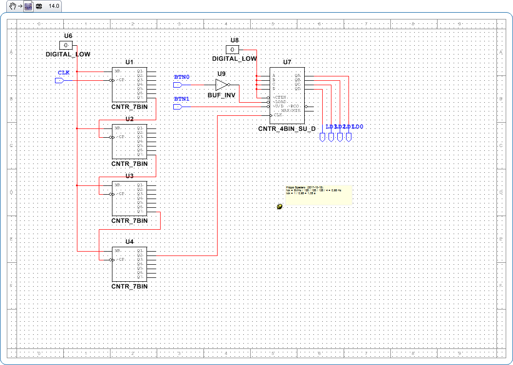
The 4-stage counter is an Up/Down Counter settable by BTN1 button on Digilent board. The counter has an asynchronous parallel load capability permitting the counter to be preset. When the BTN0 button is pressed, information present on the Parallel Data inputs (A,B,C,D are setted on 0,0,0,0) is loaded into the counter and appears on the outputs regardless of the conditions of the clock inputs.
If you want use file that I created in Multisim, you can save the schematic .PNG image that you can see on this page: so you have to click with right button of your mouse on the link and select Save image...; then open it with Multisim from File > Snippet > Open snippet file...