I am proud to know that one years after the publication (September 15, 2021) of the new edition of the book on Electrotechnics and Electronics of which I am co-author with my colleagues Enrico, Ippolito and Pierpaolo, it has been appreciated by many secondary school teachers in Italy. The books are written in Italian.

20220413 ed2018 vol1 20220413 ed2018 vol2  20220413 ed2018 vol3 


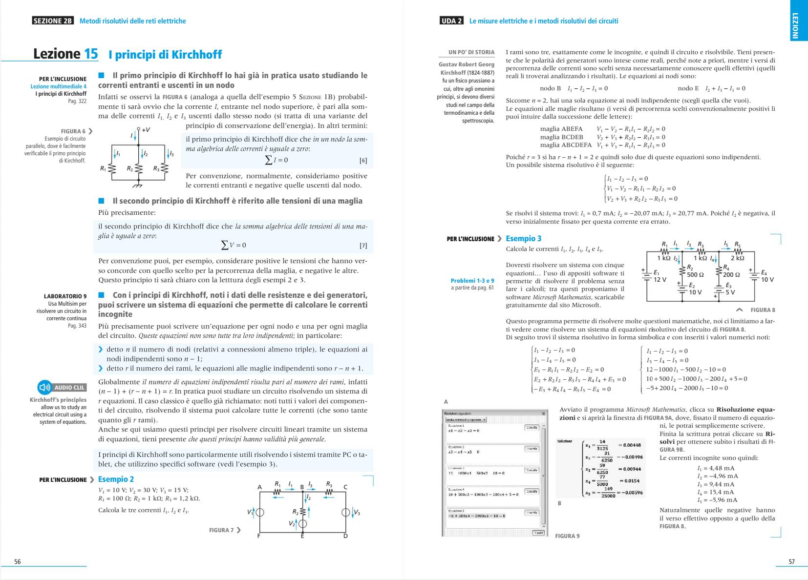
In this new edition we have reorganized the contents of the book into single topics of 2 pages for 1 hour of lessons, with 2-speed theory: the title-sentences and the colored background highlight the fast path.
Many examples allow you to apply the theory right away. The learning process is systematically assisted: videos for easy study in the ebook version, concept maps for review, problems carried out and to be carried out, all solved and with reference to the formulas and lessons. All materials to prepare for the test are always with the answers and solutions in the book.
We have also written multimedia lessons that allow, through simulations, to experiment with new teaching strategies and allow a simplified and intuitive study, even with videos, of many topics of the theory. In the book we also offer many practical workshops, with traditional proposals but also with more innovative proposals (for makers): the support files for the tutorials are always available.
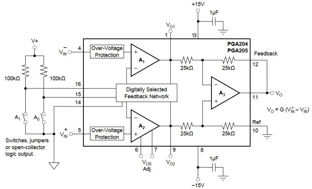
Here the lesson on the Kirchhoff's law (click to enlarge):

 20220413 ed2018 vol1 Kirchhoff

The OP-AMP classes of type VGA (Variable Gain Amplifier) ​​or PGA (Programmable Gain Amplifier) ​​extend the analog capabilities of microcontroller devices, supporting a number of analog applications with a minimum number of external components and the possibility of being configured with digital commands directly from the microcontroller.

The gain of PGAs can be controlled by external digital or analog signals such as a continuous voltage; it is common to make the gain in dB proportional to a linear voltage control and can start from less than 1V / V to over 100V / V.
Some PGAs can be configured for selectable decadic gains such as 1, 10, 100, 1000, instead others can be configured for binary gains such as 1, 2, 4, 8, etc. External digital control signals can arrive via SPI (Serial Peripheral Interface) or I²C bus; the newer PGAs can also be programmed to adjust the offset voltage, or as active filters. The most popular applications for these products are the conditioning of the signal and the sensors, the automatic control systems of the gain (AGC, Automatic Gain Control), the control of motors.

Texas Instruments' PGA204 / 205 opamps are general purpose PGA instrumentation amplifiers (for general purposes). They're available in DIP-16 format (useful for experiences in the didactic laboratory) and SOL-16 for editing superficial. Figure shows the connections necessary for their operation.

20211116 PGA204 014

Gains are digitally selected according to the scheme shown in the figure by means of two TTL or CMOS compatible address lines, indicated with A0 and A1. The PGA204 allows gains: 1, 10, 100, 1000 V / V while the PGA205: 1, 2, 4, 8 V / V. The selection inputs A1 and A0 are digital pins 15 and 16 respectively. Logic "1" is defined as a voltage greater than 2V above digital ground potential: pin 14. Digital ground is normally connected to the ground of the power supplies.20211116 PGA204 04

These opamps must be powered in dual supply, V+ to pin 13 and V- to pin 8, starting from ±4.5 V, allowing it to be used in battery systems. The quiescent current is 5mA. Precedent figure shows a basic application that allows you to select the gain of the PGA204 / 205 by means of two switches, or an open-collector logic, exploiting the pull-up resistors connected to ensure noise-free logic "1" when the switch, or the open-collector logic are open and “0” when they are closed. The scheme circuit is like of an instrumentation amplifier, in order to bring pin 10 to ground and to make the external feedback connection, connecting pin 12 to output terminal 11. The analog inputs V+ and V- are pins 4 and 5 respectively.

The rectifiers, also called simply diodes, are devices designed to have only one direction of significant conduction, said forward-bias, otherwise when they are working in reverse-bias the conduction is insignificant as long as the voltage value is not exceeded a voltage value called breakdown.
We call rectifier diode any diode used to presents reverse breakdown voltage always greater than the inverse voltage of the power supply. And the function of these diodes is in the final analysis to block any inverse current to the diode conduction.
You consider the following classification of rectifier diodes (bearing in mind that some diodes may also fall into several categories):

  • General purpose diodes used for purposes that does not require the optimization of any electrical parameter. Normally they have a few tens of volts of breakdown voltage and direct current maximum limits of some hundreds of mA. An example is the diode BAV17.
  • Switching diodes optimized to work with signals which have very fast commutations. They must present small values of recovery time. An example is the model 1N4148. Sometimes the diodes foreseen for high frequency applications (for example VHF tuners) are included in this category and it is very important that they have a small differential resistance. An example of this second type of diode is the device BA243.
  • Small signal diodes are foreseen for small currents (at most some hundreds of mA) and not very high breaking voltages (100 ÷ 200 V maximum) and not for specific uses. The 1N4148 and BAV17 diodes already mentioned above are part of this category.
  • Rectifier diodes are the rectifiers in the classical sense intended to straighten the mains voltage or in any case alternating voltages often of considerable amplitude: they are therefore foreseen for high currents and voltages. Examples are the devices 1N4001 and 1N4007. Integrated bridge rectifiers are widely used in this category.
  • Fast rectifiers-soft recovery are expected diodes to work in power application but with low switching times. They must present small recovery time values. They are particularly suitable for switching power supplies. An example is the BYG20D.


Ideal diode

If we apply a voltage to the ideal diode with the potential of the anode higher than the cathode, the device works in forward-bias (a) and has zero resistance, but if the anode potential is less than the cathode, the diode operates in reverse-bias (b) and has infinite resistance.

More precisely, the ideal diode behaves as a null resistance if it is forward-bias (a) and therefore the current flowing on it is worth I = V / R. It behaves instead of infinite resistance if it is reverse-bias (b) and therefore the current is worth I = 0.

The diode can be considered as a particular case of non-linear resistor. Although the device category of nonlinear circuits is very wide and requires generally methods of investigation of considerable complexity, the most important diode circuits in electrical and electronic applications do not always require excessive conceptual complications for their understanding. There are different categories of diodes, among these the most significant are:

  • rectifiers diodes;
  • zener diodes;
  • diodes LED;
  • photodiodes;
  • varactor diodes;
  • Schottky diodes.

Now I propose you a test on PN, LED and zener diodes: https://forms.gle/BgKaft8GDvSE93Ts8 Try it!

See the simple circuit in figure, there are three circuit elements: the resistor, the electric generator and the ground, in addition to the connecting wires.
If you want to use the circuit already built, you can save this PNG image and load it with Multisim 14 or later using File > Snippets > Open snippet file.

Simple electrical circuit Let's analyze them in detail. The generator in our case is a battery that provides DC voltage; the voltage of a generator, also known as electric potential difference, is measured in volt [V] and in this case it is worth 12 V. This generator is a bipolar component because it has two terminals. Generators are part of the so-called active components (provide energy).
The resistor is also a bipolar component and the electrical parameter that characterizes it is the resistance. It is measured in ohm [Ω] and in our case it is 1 kΩ. The resistor is one passive component because it consumes energy.
The third element characterizing the circuit is the ground. It is not a component but rather a symbol inserted in the circuit to indicate a point of zero potential.

20170918 Simple electrical circuit 3
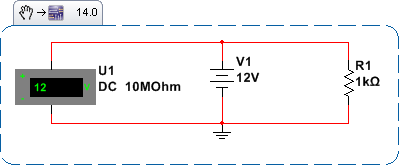
What can we expect from this circuit? There is an electric potential difference provided by a generator, inserted in a closed circuit (the path of the wire starts from the positive pole and closes to the negative pole) so you can expect a current to flow inside!
Before you see if it is true, it is better to check that there is tension. To do this we should connect a voltmeter between the + and - of the generator, as shown in the figure to the side. This is called a parallel type conection.
Multisim confirms that there is voltage and it is useful to note that this voltage is the same for the resistor. We can see that the generator, resistor and voltmeter are in parallel, so we can conclude that several parallel elements all have the same voltage.

Simple electrical circuit
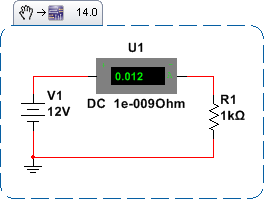
Let's go back to the current now and see if it's there. To do this we will have to insert an ammeter along the path of the circuit as in the figure.
We can say that at all points of the circuit the current is the same, or the battery, the ammeter and the resistor are all crossed by the same current. Several components crossed by the same stream are said in series.
This is a very simple circuit and a bit special: the battery and the resistor are in series because they are crossed by the same current but are also in parallel because they have the same tension on their sides!

Advertising

Advertising

Advertising

We use cookies

We use cookies on our website. Some of them are essential for the operation of the site, while others help us to improve this site and the user experience (tracking cookies). You can decide for yourself whether you want to allow cookies or not. Please note that if you reject them, you may not be able to use all the functionalities of the site.