circuito bingo

Tombola is a traditional Italian board game that is usually played with the family during the Christmas holidays. Bingo is a game of chance played all over the world (in the USA the game is played with 75 numbers).

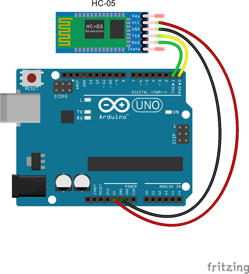
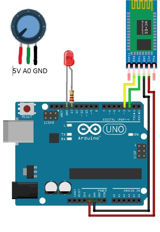
We program with Arduino a sketch that implements a C function that generates a succession of 90 bingo or tombola numbers. To test the feature of this function, each time you press a button (with debounce) the software prints a new number. The extraction of numbers can also be carried out with automatic extraction, for example every 5 seconds inside the loop(). The circuit diagram is minimal, as you can see in the figure.

In the sketch shown, the proposed function int* getNumbers() returns the pointer to the memory location *RAMlocation from which the vector of the extracted numbers, called bingo[90], is stored. Each time you press a button (with debounce), connected to pin 4, the software prints a new, not yet extracted, number.


/* Function that generates a sequence of 90 bingo numbers. 
Each time you press a button (with debounce) the software 
prints a new number */
#define pushButton 4
int bingo[90];
int *RAMlocation;
int i;
int presentState, previousState=0;

int* getNumbers(){
  static int numbers[90], extractedNumber;
  int i=0,k;
  randomSeed(analogRead(0));
  bool alreadyExtracted;
  do {
      alreadyExtracted = false;
      extractedNumber = random(1, 91);
      for (k=0; k<i;k++) {
        if (extractedNumber == numbers[k]) {
              alreadyExtracted = true;
            }
       }
       if (alreadyExtracted == false) { 
            numbers[i]=extractedNumber;
            i++;
          }
    } while(i<90);
  return (&numbers[0]);
}

void setup(){    Serial.begin(9600);    RAMlocation = getNumbers();  for (i = 0; i < 90; i++) {      bingo[i]=*(RAMlocation + i);      /* The following two lines are for debugging:      you can remove them */      Serial.print(bingo[i]);      Serial.print(" ");      }    Serial.println();  pinMode(pushButton, INPUT);  i=0; } void loop() {  presentState=digitalRead(pushButton);  if ((presentState==1) && (previousState==0))  {    Serial.print(bingo[i]);    Serial.print(" ");    i++;  }  previousState=presentState; }

Here you can find the simulation of the Arduino sketch with Tinkercad: Tombola function (Bingo). I also propose a simple code in ANSI C that you can try with Ideone: tombola.c or other C compiler.

#include <stdio.h>
#include <stdlib.h>
int tombola[90], estratto;
int i=0,k;
int giaestratto; // boolean<
int mainvoid) {
  srand(time(NULL));
  do {
    giaestratto=0;
    estratto = rand()%90+1;
    for (k=0; k<i;k++) {
      if (estratto == tombola[k])
          {
            giaestratto=1;
          }
    }
     if (giaestratto==0) { 
          tombola[i]=estratto;
          printf("\t%d",tombola[i]);
          i++;
        }
  } while(i<90);
}

I propose to measure ambient temperature and humidity with DHT11 connected to Arduino Uno and send the data to my smartphone via Bluetooth using the HC-05 board. The app is programmed with App Inventor. The same app allows me to send an on-off command to turn the LED_BUILTIN on the Arduino board on or off.

20220407 LED e DHT11 schema 

 20220407 LED e DHT11 mobile


I think to program the acquisition, data processing and visualization interface as shown below.
20220407 LED e DHT11 app

#include <SoftwareSerial.h>
#include <DHT.h>
#define intervallo 2000  // intervallo per il millis

DHT dht(4, DHT11);
SoftwareSerial Bluetooth(2, 3); // RX, TX

char Incoming_value = 0;    // LED On = 1 / Off = 0
unsigned long tempo = 0;    // tempo precedente per il millis
String temperatura, umidita; // valore acquisito dal DHT11 dopo casting

void setup() 
{
  Serial.begin(9600);    // seriale USB     
  pinMode(13, OUTPUT);      //LED BuilT In
  dht.begin();  
  Bluetooth.begin(9600); // set the data rate for the SoftwareSerial port
}

void loop()
{
  // gestione dati  
  
   if ((millis()-tempo)>intervallo)
  {
  temperatura = String(dht.readTemperature());
  Bluetooth.print(temperatura); // invia al Bluetooth
  Serial.print("temperatura: ");
  Serial.print(temperatura);

  Bluetooth.print("-");   // invia al Bluetooth come discriminante
  
  umidita = String(dht.readHumidity());
  Bluetooth.print(umidita); // invia al Bluetooth
  Serial.print(" - umidità: ");
  Serial.println(umidita);
  
  tempo = millis();
  }
  
  // gestione LED On/Off
  if(Bluetooth.available() > 0)  
  {
    Incoming_value = Bluetooth.read();      
    Bluetooth.print("\n");        
    if(Incoming_value == '1')             
      digitalWrite(13, HIGH);  
    else if(Incoming_value == '0')       
      digitalWrite(13, LOW);   
  }                            
} 

Here you can download the material to develop the application: PDF step by step , Arduino sketch, App Inventor AIA.

In february I and my colleague Cesare at IIS Maxwell did some laboratory tests for a group of lessons with students on the interface between the DJI Tello drone and the ESP32 development board. Cesare found this very useful Arduino library for controlling DJI tello through ESP32 Module: https://github.com/akshayvernekar/telloArduino

Here is a video with our test to manage Tello with ESP32 via WiFi: https://youtu.be/nJEaAHfHlhw When the Tello enters the range of the ESP32 card, it connects to the drone network, obtaining an IP address. Here a simple sketch included in the tello.h library

#include <Tello.h>

// WiFi network name and password:
const char * networkName = "TELLO-DC57BC"; //Replace with your Tello SSID
const char * networkPswd = "";

//Are we currently connected?
boolean connected = false;

Tello tello;

void setup() 
{
  Serial.begin(9600); 
  //Connect to the WiFi network
  connectToWiFi(networkName, networkPswd);
}

void loop() 
{
  Serial.println("Pronto");
  // put your main code here, to run repeatedly:
  if(connected )
  {
    tello.takeoff();
    delay(5000);
    tello.up(30);
    delay(2000);
    tello.down(30);
    delay(2000);
    tello.right(30);
    delay(2000);
    tello.left(30);
    delay(2000);
    tello.land();
    //you have 5 seconds to save your tello before it takes off again
    delay(5000);
  }
}

void connectToWiFi(const char * ssid, const char * pwd) 
{
  Serial.println("Connecting to WiFi network: " + String(ssid));

  // delete old config
  WiFi.disconnect(true);
  //register event handler
  WiFi.onEvent(WiFiEvent);

  //Initiate connection
  WiFi.begin(ssid, pwd);

  Serial.println("Waiting for WIFI connection...");
}

//wifi event handler
void WiFiEvent(WiFiEvent_t event) 
{
  switch (event) 
  {
    case SYSTEM_EVENT_STA_GOT_IP:
      //When connected set
      Serial.print("WiFi connected! IP address: ");
      Serial.println(WiFi.localIP());
      //initialise Tello after we are connected
      tello.init();
      connected = true;
      break;
      
    case SYSTEM_EVENT_STA_DISCONNECTED:
      Serial.println("WiFi lost connection");
      connected = false;
      break;
  }
}

I want to manage sensors and actuators connected to Arduino Uno, through a simple smartphone application, using a Bluetooth module, which uses short-range radio waves to put two neighboring devices are communicating. A hand for programming mobile apps is given to us by App Inventor, a development environment with a graphical interface, simple and intuitive for those who already know the world of coding programming. To practice with App Inventor and Arduino programming, I refer you to the respective websites and reference guides.

Exercise 1
Basic application that allows you to turn on LED 13 on the Arduino board from your mobile phone.

bluetooth hc 05 arduino bb  cellulare esercizio1 LED 

Remember that before connecting to Arduino with Bluetooth, using the app you just created with App Inventor, you must pair the Bluetooth of your mobile phone with the HC-05 board. To do this, first go to your mobile phone settings and find your HC-05 card in the list of detected devices, then pair it with password 1234.
Here the material to develop the application: PDF step by step , Arduino sketch, App Inventor AIA.

Exercise 2
Here I briefly show you an application that allows you to turn on LED 13 on the Arduino board from your mobile phone and at the same time receive a byte (an integer between 0 and 255) acquired by an Arduino analog pin on your smartphone. The analog inputs of Arduino are 10 bits (between 0 and 1024) but it is possible to compress the acquisition on 8 bits in order to divide the acquired value by 4.

 cellulare esercizio2 LED potenziometro schema  cellulare esercizio2 LED potenziometro

In this Arduino sketch I use SoftwareSerial library that allow serial communication on other digital pins of the Arduino, rather than pins 0 and 1 (which also go to the computer via the USB connection).
Here the material to develop the application: PDF step by step , Arduino sketch, App Inventor AIA.

Exercise 3
Like Exercise 2, with the only difference that now the mobile phone receives an integer between 0 and 1023 acquired from an Arduino analog pin. Now the app on your smartphone not only reads one byte at a time sent to it by Arduino, but all the bytes that are sent to it.
Here the material to develop the application: PDF step by step , Arduino sketch, App Inventor AIA.


C3730372 01 002

Today in the laboratory I propose to electronics students in the fifth year of secondary school to experiment with a PT100 resistance thermometer. We want to measure the temperature detected with PT100 in the range between 0 and 100 °C and acquire it with Arduino Uno witch ADC has input dynamics between 0 and 5 V.

We use a transducer like the one in the figure, purchased from RS, an important electronics distributor who has shop near my home. Here I report the technical sheet: Platinum Resistance Temperature Sensors.

Conditioning is based on the use of the resistive Wheatstone bridge and the differential amplifier with LM741 or TL081 opamp. These opamps require dual power supply.
We connect the PT100 in 2-wire connection mode and calculate that for measurements in the range between 0 and 100 °C its resistance varies between 100 Ω and 138.5 Ω. We choose the other resistances of the bridge: two of 1 kΩ and one of 100 Ω which serves as a reference for the measurement of the PT100 at 0 °C. In the diagram we report our conditioning. The VB voltage is set at 450 mV as a measurement reference, while the VA voltage detected on the voltage scores with the PT100 can vary between 450 mV and 610 mV.

Our analysis for the Arduino sketch considers that the resistive variations of the PT100 are in the order of mΩ and consequently also the voltage variations measured on the VAB bridge are small (in the order of mV) while on the contrary the floating point calculations performed by Arduino they are poor in resolution (two decimal places); so we prefer to program the calculations in Arduino working in mV, ie translating VO into mV rather than Volt.

// PT100 range 0 - 100 °C using 
// Wheatstone bridge and differential 
// amplifier with LM741

int pt100;
float Vab, Va, Vo, Rpt100, T;

void setup()
{
  Serial.begin(9600);
}

void loop()
{
 pt100 = analogRead(A0);     // 10 bits code
 Vo = pt100/1024.00*5000.00; // voltage in mV
 Vab = Vo/31.91;    // amplifier gains: 150k/4.7k=31.91
 Va = Vab+454.54;   // bridge reference voltage in mV: 
                    // 5V*100/(1k+100)
 Rpt100 = (Va*1000.00)/(5000.00-Va);  // PT100 voltage in mV: 
                          // 5V*Rpt100/(1k+Rpt100)
 T = (Rpt100-100)/0.385;  // pt100 transducer relationship:
                          // Rpt100=100*(1+0.00385*T)
 Serial.print("T: ");
 Serial.print(T);
 Serial.print(char(176));
 Serial.println("C");
 delay(1000);
}

And then also a simulation with Tinkercad where the PT100 is simulated with the series of a 100 Ω resistor and a potentiometer set with a maximum of 38.5 Ω: https://www.tinkercad.com/embed/83ENtZz1e8k (in the Tinkercad window, open the code section and activate the serial monitor before starting the simulation to view the temperatures detected when you turn the potentiometer).

Advertising

Advertising

Advertising

We use cookies

We use cookies on our website. Some of them are essential for the operation of the site, while others help us to improve this site and the user experience (tracking cookies). You can decide for yourself whether you want to allow cookies or not. Please note that if you reject them, you may not be able to use all the functionalities of the site.